



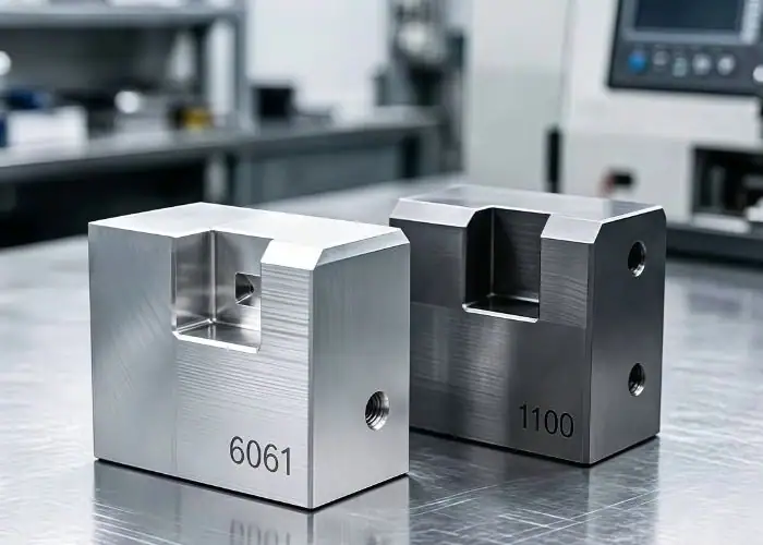
A 6061 aluminum component can appear correct during machining and change after release. An in-process probe confirms position and a cut face looks flat against the fixture. Later, the part rocks on a surface plate or a mating component no longer fits.
This does not automatically mean the machine was inaccurate. Material condition, geometry, clamping, cutting sequence, and inspection state can interact. The real question is whether the part remains functional after manufacturing forces are removed.
The Fixture Can Hide Distortion Instead of Preventing It
A fixture locates and supports the workpiece, but excessive or uneven clamping can force a bowed blank or flexible wall into another shape.
The machine then cuts the constrained geometry.
While the part is clamped:
- the profile is pressed against locating pads;
- a flexible wall may appear straighter;
- an in-process probe can report stable coordinates;
- critical features are created relative to the restrained condition.
After the clamps are released:
- the external force disappears;
- the part seeks a new free-state shape;
- previously separated features can move relative to one another;
- flatness, profile, or assembly alignment may change.
More clamping force is not always safer. A good fixture resists cutting loads without changing the part’s functional condition.
Four Forces Can Move a 6061 Part After Machining
Movement usually comes from interacting factors rather than one isolated cause.
Influence
How it acts
Possible symptom
Engineering review
Material condition
Stress or variation within the supplied stock becomes apparent during removal
Shape changes after roughing or release
Verify alloy, temper, stock form, and incoming condition
Part geometry
Thin walls, deep cavities, or asymmetric sections lack balanced stiffness
Bow, twist, or local flatness change
Balance wall geometry and material removal
Workholding
Clamps distort flexible areas or locate from unstable surfaces
Part passes while restrained but fails when free
Review supports, clamp positions, sequence, and force
Cutting sequence
Heavy one-sided removal changes the remaining structure
Dimensions drift between operations
Separate roughing and finishing; reassess datums
The table is a diagnostic starting point. Tool condition, temperature, programming, and measurement should also be reviewed.
6061-T6 Is Machinable, but It Is Not Automatically Stable
6061-T6 CNC machining is practical because the alloy combines machinability, strength, corrosion resistance, and finishing compatibility. Yet “machinable” does not mean immune to movement.
Plate, bar, and extrusion stock can have different histories and geometric conditions. Temper must be confirmed, not inferred from the alloy number. Correct stock can still move when a thin, asymmetric design is heavily clamped and machined mainly from one side.
Material documentation confirms what was supplied, not whether the route is stable. Engineers can review 6061 aluminum machining behaviour before finalising stock, wall, tooling, finishing, and dimensional-control decisions.
Design Decisions Should Reduce Distortion Before CAM Begins
Many stability problems are easier to reduce in CAD.
Balance Wall Thickness and Material Removal
Check whether the design:
- leaves one side heavy while the opposite side becomes thin;
- contains abrupt transitions between rigid and flexible areas;
- requires most material to be removed from one face;
- provides finishing allowance on functional surfaces;
- leaves adequate support around deep pockets and openings.
Perfect symmetry is unnecessary, but cutting sequence should influence walls, ribs, and cavities.
Give the Fixture Stable Locations
A part should offer accessible, repeatable datums. Thin walls, flexible arms, and cosmetic faces are poor locating choices unless the fixture accommodates them.
Process pads or sacrificial extensions can improve workholding but must be justified against material and removal requirements.
Tighten Only What Controls Function
Mounting faces, seals, locating bores, mating slots, and aligned holes may justify close control. Hidden clearance surfaces and nonfunctional pockets may not.
Overconstraining every feature increases effort and sensitivity to movement that does not affect function.
A Stable Route Separates Roughing, Release, and Finishing
For a sensitive component, the route may need to reveal movement before finishing.
- Verify incoming stock and its locating condition.
- Establish an initial datum for roughing.
- Remove major volumes while retaining critical allowance.
- Release or reduce restraint to expose movement.
- Re-establish functional datums after roughing.
- Semi-finish critical geometry in controlled stages.
- Finish functional interfaces from verified references.
- Inspect the relevant free state used for acceptance.
Not every part needs all eight stages. The sequence matters more as walls thin, removal becomes unbalanced, or feature relationships tighten.
Failure Patterns Can Reveal Where Stability Was Lost
Failure pattern
Possible explanation
Recommended check
Dimensions pass in the fixture but fail after release
Clamping temporarily changes the workpiece shape
Compare restrained and free-state measurements
The first article passes but later parts drift
Tool, loading, fixture, or incoming-stock conditions are changing
Review in-process checks and trend data
Individual dimensions pass but assembly is misaligned
Machining and inspection use references different from functional interfaces
Align the datum strategy with assembly
The part fits before finishing but not afterwards
Finish allowance or masking was not considered
Verify critical features in the delivered condition
Relationships change after a second setup
Reorientation accumulates locating variation
Reduce setups or reference stable machined datums
These patterns help guide investigation. They should not be used to blame the alloy before the complete manufacturing and measurement route is reviewed.
The Supplier Should Explain How Repeatability Is Created
A useful manufacturing review should explain the proposed 6061 stock form and temper, initial datums, clamping approach, roughing and finishing sequence, inspection points, and controls used during repeat production.
Buyers should expect clarity on:
- how thin or flexible features are supported;
- which surfaces establish each setup;
- when the part is measured after release;
- which dimensions are monitored for drift;
- which features are verified after finishing;
- how the route changes from sample to production quantities.
Projects involving thin walls, multiple setups, critical interfaces, or recurring orders benefit from CNC process engineering for repeatable aluminum parts that connects DFM, fixturing, machining, and inspection.
A Successful Prototype Can Mislead the Production Team
A prototype proves that a part can be made, not that the route is ready for repetition. A skilled operator may adjust one setup manually, inspect every feature, and correct a local issue. Production introduces repeated loading, tool wear, changing stock lots, sampling plans, and schedule pressure.
Before scaling, verify fixture repeatability, tool-life assumptions, in-process measurement, finishing effects, and realistic material variation. Sample success should lead to process validation rather than automatic duplication of the prototype method.
Inspection Must Measure the State That Matters
In-fixture probing supports process control but cannot replace free-state verification when the released condition controls assembly. CMM alignment should reproduce drawing datums rather than conceal displacement with a convenient best fit.
Inspection may combine:
- in-process probing for tool or setup control;
- free-state dimensional inspection;
- datum-based CMM measurement;
- functional gauges representing mating geometry;
- final checks after anodizing or coating.
Measure the condition in which the customer will use the part—not only the condition that is easiest to inspect.
Dimensional Stability Is Designed Into the Process
6061 is versatile, but its designation alone cannot keep a component stable. Stock condition, geometry, clamping, removal balance, datum transfer, and inspection all influence the result.
A fixture can support a part or hide movement. A prototype can validate geometry or conceal dependence on manual adjustment. An inspection report may confirm function or only the restrained measurement state.
Reliable 6061 aluminum machining reviews these relationships before production. Designed around the free and functional state, accuracy remains meaningful when the component is released, finished, inspected, and assembled.