



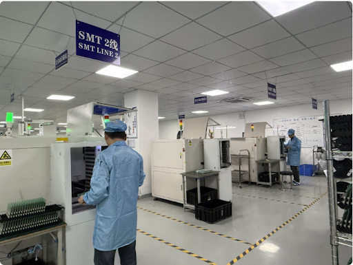
An industrial control board can pass a bench check and still fail when it switches a relay and exchanges data over a long cable at the same time. The first small batch is a chance to catch that interaction while you can still change the board, the firmware, or the production test. Before placing the order, write down what each board must do, what evidence you expect back, and which failures should put the batch on hold.
In this guide: Define the operating conditions · Approve substitutions · Verify workmanship and behaviour · Set the release rules · Frequently asked questions
Define the Conditions the Board Will See in Service
Start at the cabinet terminals. Record the power input range, field wiring, communication settings, connected loads, and expected behaviour after a power interruption. A nominal 24 V label describes the supply family. Your product specification determines the limits the board actually has to meet. Agree on where voltage is measured, since the voltage at the bench supply can differ from the voltage at the board connector when an output switches.
Define the expected state of each output during startup, reset, and loss of communications. For example, a relay that drops out during a controller reset may behave correctly in one machine and cause an unacceptable interruption in another. Use the system requirements to define the expected state and how quickly it must be reached. During industrial control PCB assembly planning, put these decisions into the test instructions so the assembler and the product team judge the same behaviour.
If the board uses RS-485, document the cable, baud rate, and intended bus topology. Specify where termination belongs and whether it is enabled on the unit under test. A short, direct bench connection is useful for finding basic faults. A representative harness and bus setup give you better evidence about how the board will behave in the cabinet.
Approve Substitutions by the Function They Affect
A proposed alternate can match the footprint and still change how the product behaves. For a relay, compare coil current and pickup and dropout characteristics, plus contact ratings for the actual load type. For an RS-485 transceiver, check the pinout, supply and logic compatibility, receiver behaviour when the bus is idle, and supported data rate. For a terminal block, check the mating part, pin orientation, and whether the wiring can be installed inside the enclosure.
Give each critical alternate a simple disposition: approved, approval required, or prohibited. For approved parts, record the exact manufacturer part number, where it can be used, and any extra check it triggers. A relay substitution might require repeating the loaded switching test. If the pilot uses two approved relay variants, record which variant went onto each serial number. That lets you compare failures by part variant without relying on memory or guessing from a photo.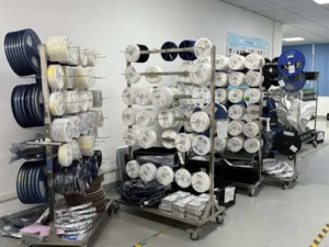
Record the exact part fitted when more than one variant is approved for the build.
Verify Workmanship and Powered Behaviour Separately
Make two sections in the acceptance sheet. The first covers assembly workmanship, including component placement, polarity, and visible solder joints. Automated optical inspection can help with visible features when the inspection programme is set up for the board. The second covers powered behaviour, including startup, input recognition, output switching under load, and communication. A board can meet the visual inspection criteria and still have the wrong firmware, an incorrect bus configuration, or a reset that only appears under load.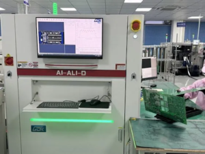
Workmanship inspection and powered acceptance checks answer different questions.
Suppose a 30-board pilot uses a 24 V input, four relay outputs, and an RS-485 link to a supervisory controller. The following checks illustrate how to write an acceptance sheet. Choose actual limits, loads, durations, and sample sizes from the product requirements.
| Check | Test condition | What to record |
| Start and recover | Power up at the defined low and high input limits. Interrupt and restore power as specified. | Input voltage at the connector, boot result, recovery time, and observed output states. |
| Switch a loaded output | Use the agreed representative load while the controller exchanges messages. | Output response, any unexpected reset, and any communication errors during switching. |
| Recover communications | Interrupt and restore the bus using the intended cable and termination setup. | Time to resume valid messages and whether the outputs follow the specified loss-of-communication behaviour. |
| Confirm the fitted variant | Read the installed firmware ID and compare the fitted relay or transceiver against the build record. | Board serial number, hardware revision, firmware ID, and critical part variant. |
Write the expected result beside each procedure. “Communications OK” is too vague to reproduce. Instead, specify which messages the board must answer, how long the test runs, and how errors are counted. Agree which checks are required on every unit and which need a smaller engineering sample. Longer cabinet tests can be separate from the production checks as long as their role in releasing the batch is clear.
Decide When to Release the Rest of the Batch
Agree on a hold point before the remaining boards are assembled or shipped. For example, you might authorise three initial units from the planned build, review the test records, and then release the remaining 27. With low-volume PCB assembly, discuss this split before work begins so the supplier can plan material staging and test time. Three passing units can establish that the agreed setup works on those units. Continue the required checks on the rest of the batch.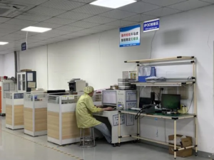
Review the first units against the same acceptance sheet that will be used for the remaining batch.
Decide in advance which results stop the run. An unexpected output transition at startup, a firmware mismatch, or an unapproved critical substitute should trigger review. Keep the first failure and its test conditions in the record, even if a board later passes. If the team changes a part, firmware setting, or test procedure, document the change, identify which boards it affects, and repeat the relevant checks before release.
Frequently Asked Questions
Is a working prototype enough to approve the small batch?
A prototype establishes that one build can work. Test the first production units with the parts, firmware, and wiring intended for the batch so that changes since the prototype are covered.
Do all boards need the same tests?
Give every unit the checks needed for individual acceptance, such as firmware verification and core input and output functions, where required by the product plan. Define the sample and acceptance criteria separately for extended tests.
What should come back with the boards?
Ask for the as-built revision, firmware version, approved deviations, and test results linked to board serial numbers or the agreed lot identifier. These records help reproduce a failure and prepare the next order.