



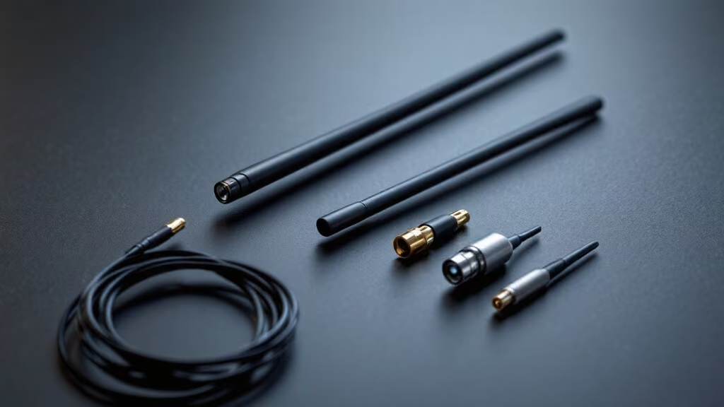
Communication antenna is a type of energy converter that transforms guided waves propagating along a transmission line into electromagnetic waves propagating in unbounded media, or performs the reverse transformation. For designing a low-power, short-range 2.4GHz wireless transceiver device used in RF systems, antenna design and selection are important parts, and a good antenna system can enable communication distance to reach its optimal state. There are many types of 2.4GHz antennas, and different applications require different antennas.
Communication Antenna Categories
So how do you select a 2.4GHz antenna suitable for your wireless transceiver device from the many 2.4GHz antennas available? Next, we will introduce how to choose a 2.4GHz antenna through the classification and comparison of 2.4GHz antennas. The antennas mainly used in the 2.4GHz band include ceramic antennas, PCB antennas, and spring antennas. Ceramic antennas and PCB antennas are internal antennas, while spring antennas are external antennas.
1. Ceramic Antennas
The working principle of ceramic antennas uses GPS satellites to achieve navigation and positioning, while the main task of the user’s receiver is to extract the pseudo-random noise code and data code from satellite signals, so as to further calculate navigation information such as the position, velocity, and time (PVT) of the receiver carrier. The principle of ceramic antennas should be explained in two parts: one is the transmitting antenna, and the other is the receiving antenna. General antennas are reversible and can serve as both transmitting and receiving antennas. Simply put, a ceramic antenna transmitting antenna converts the high-frequency electric field formed between the antenna and the ground into electromagnetic waves through an electrode called an “antenna,” so that they can be radiated outward and propagate far away. Simply put, a ceramic antenna receiving antenna senses electromagnetic waves coming from the air as an electric field through an electrode called an “antenna,” generates a high-frequency signal voltage, and sends it to the receiver for signal processing. In the design of the ceramic antenna unit, a high-frequency, low-noise amplifier is used to reduce the influence of antenna thermal noise and the preceding unit circuits on receiver performance. The role of the ceramic antenna is to convert the electromagnetic wave energy of the radio signal transmitted from the satellite into current that can be captured and used by the receiver’s electronic devices, so the size and shape of the antenna are very important, because these determine the ceramic antenna’s ability to capture weak electromagnetic wave signals.
A ceramic antenna is a miniaturized antenna suitable for Bluetooth devices. Among IoT products, the most commonly used are GPS, Bluetooth, and GSM ceramic antennas. Ceramic antennas are divided into block ceramic antennas and multilayer ceramic antennas. A block antenna is made by sintering the entire ceramic body at high temperature in one step and then printing the metal part of the antenna on the surface of the ceramic block. Multilayer antenna firing adopts low-temperature co-firing: after aligning and stacking multiple ceramic layers, they are sintered at high temperature, so the metal conductor of the antenna can be printed on each ceramic dielectric layer according to design requirements. In this way, the antenna size can be effectively reduced, and the purpose of hiding the antenna can be achieved.
Because the dielectric constant of ceramic itself is higher than that of PCB circuit boards, using a ceramic antenna can effectively reduce antenna size. In terms of dielectric loss, ceramic dielectric also has lower dielectric loss than PCB circuit boards, so it is very suitable for use in low-power-consumption Bluetooth modules. The size of a ceramic antenna is generally comparable to the 1210 package, and its effect is stronger than that of an onboard antenna. It is also relatively convenient to use. Generally, it has an ANT pin and a ground pin. During PCB design, the area around the antenna must be kept clear, and especially copper must not be poured there. At the same time, when using a ceramic antenna, attention must also be paid to the matching problem of the balun circuit. If a dedicated integrated circuit is used, it is best to have the manufacturer test the matching between the balanced circuit and the ceramic antenna. If the matching is poor, it will also affect the antenna’s effect.
The advantages of ceramic antennas are that they occupy very little space and have relatively good performance. The disadvantages are that it is difficult to achieve multiband operation, so it is difficult to apply them in 4G-type products. There are relatively high requirements for circuit board clearance, so they are not suitable for particularly compact products.
2. PCB Antennas
A PCB antenna refers to the part of the PCB used for wireless reception and transmission. When transmitting, it converts the high-frequency current of the transmitter into spatial electromagnetic waves; when receiving, it converts the electromagnetic waves obtained from space into high-frequency current and inputs it to the receiver. When using a PCB antenna, attention must also be paid to the matching problem of the balun circuit. If a dedicated integrated circuit is used, it is best to have the manufacturer test the matching between the balanced circuit and the PCB antenna. If the matching is poor, it will also affect the antenna’s effect.
PCB antennas are widely used in Bluetooth modules, industrial-grade WIFI modules, [ZIGBEE modules], [LoRa modules], and other single-band module circuit boards.
The advantages of PCB antennas are that they occupy less space, have low cost, do not require separate antenna assembly, are not easy to damage by touch, and facilitate whole-device assembly, but they sacrifice performance. The disadvantages are that it is difficult for a single antenna to achieve a round radiation pattern, insertion loss is high, efficiency is relatively low, and they are susceptible to interference from the mainboard; at the same time, they are only suitable for a single band, such as Bluetooth modules and WiFi modules; PCB antenna performance may vary somewhat between different batches.
3. External Antennas
External antennas are mainly connected to external antennas by being directly soldered to the antenna (ANT) pin, IPEX connector, or SMA connector. The IPEX antenna connector and SMA antenna connector are interfaces for RF circuits and antennas and are widely used on boards of wireless LAN-related products.
There are many types of external antennas, such as spring antennas, FPC antennas, short rubber rod antennas, long bendable antennas, suction cup antennas, and other external antennas. The advantages of external antennas are that the radiation pattern can be better controlled, insertion loss is low, signal directivity is good, efficiency is high, and anti-interference capability is strong; they can reduce interference from the mainboard, and they do not require too much debugging and matching. If there is a mismatch between the wireless transceiver device and the external antenna, it can also be solved by directly replacing the external antenna without replacing the PCB board. The disadvantages are higher cost and relatively troublesome assembly.